| Shourt Line by Soft Works Ltd. | |||||
Model Railroad Products |
|||||
SL 8453018 Micro Size LED controller wired & ready to use w 18" cables + Two Free spring loaded 2 conductor terminal blocks for EZ no tool, no soldering required installation
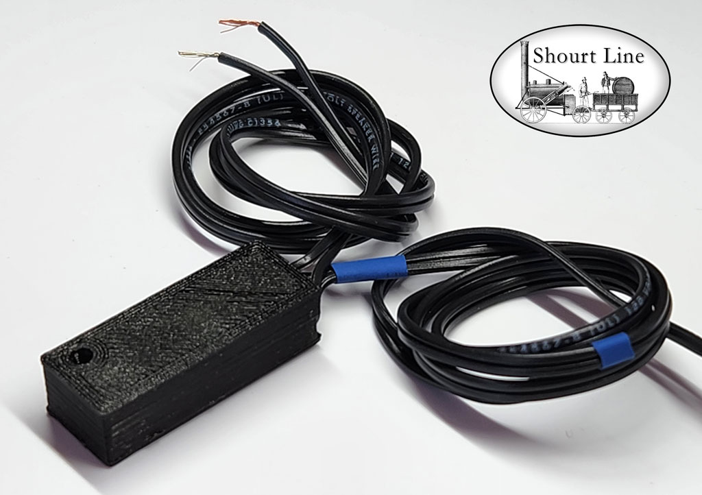
The SL 8453018 comes with a case and removable bottom lid with an installed SL 8452024 3Amp adjustable voltage regulator wired to an SL full wave bridge rectifier and 2ea 18 inch micro black 24 AWG cables for DC, AC or DCC track power IN and LED power OUT at 3.05 Volts for up to 200 LEDs. The case top has a recessed hole for access to a pot for adjusting the output voltage and dimming LEDs. Two FREE spring loaded 2 conductor terminal blocks are included for an easy solderless installation.
Buy it now price: $39.95 NEW
Features:
Easy install - Works with any LED SL lighting fixture that requires an SL LED controller or any bare white LEDs of your choice.
Features:
- Wired and ready to power >100 white LEDs
- No soldering required
- Micro Size fits where other products do not.
- Power 1 to 200 LEDs in parallel Without dropping resistors
- Shourt Line LED controller are the ONLY efficient way to power from BOTH Analog and DCC (AC) power
- Cool operation
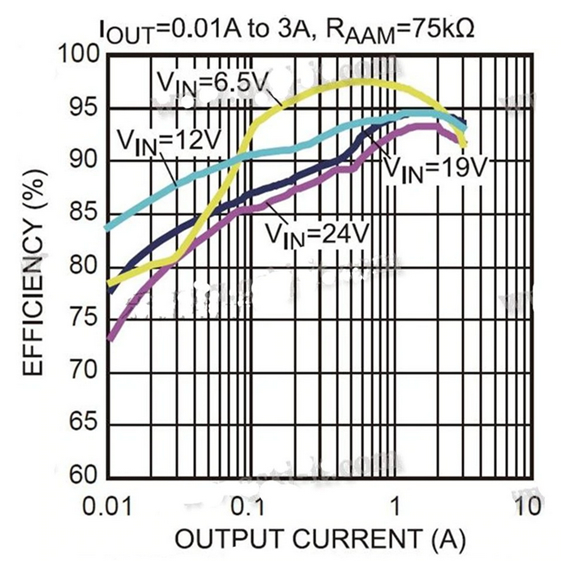
- Up to 97% efficient
- 6X less current requirement than any other products when used with SL LED lighting products
- Built in efficient Dimmer
- Built in speed control
- Adjustable Regulated Output
- Power from an unregulated or variable (analog track) input voltage
- Power Motors, Locos, Trolleys, Smokers, Bulbs, Servos, Crossing Guards, Bulbs, LEDs, and Accessories
- Fast, easy, fool-proof loco, car, building and track side lighting
- Adjustable pot allows LED & light dimming + speed control of motors or locos
- Short Circuit Protection with auto restart on removal of short circuit
- Easy hookup
- 1 year warranty
Specifications:.
- Input Voltage:DC 4.5-24V
- Output Voltage: integration adjustable and fixed output, back side can choose fixed output voltage
- Adjustable Range:0.9-4.2V,fixed voltage (1.8V 2.5V 3.3V 5V 9V 12V fixed options set to 5V) Output sent at factory to 3.05V (VD+)
- Output Current: A (max),actual testing input 6V output 2A
- Transform Efficiency:97.5%(max) (6.5 to 5V 0.7A)
- Switch Frequency:500KHz
- Output Ripple Wave:20mV (12V to 5V 3A) 20m band width
- Operating Voltage:-40 Celsius-85 Celsius
- Output Over voltage Protection: no
- Static Current:0.85MA
- Load Adjust Rate:±1%
- Voltage Adjust Rate:±0.5%
- Dynamic Response Speed% 200uS
- Output Short Circuit Protection: yes
- Input Transposition Protection: yes
- EN Enable Control: yes (ground to stop output)
- Connecting Type: 2ea 18" cables
- ~, ~ Bridge Input 18 inch 24AWG cable
- +, - Bridge out to IN+ GND on regulator
- VD+ (input +), GND Output 18 inch 24AWG cable
- Soldering Hole Space:2.54mm
- Size: 34mm L x 13mm W x 9.25mm H (1.34"L x 0.5"W x 0.37"H)
- Efficiency: Up to 97% at low track voltage (<6.5 volts yellow line below)
This chart shows the high efficiency of the SL 8452024 controller at different input voltages and output currents The controller maximum output current is 3 amps..
Why should I use an LED controller for DCC power?
- Even the the best decoders only provide +5, +10, and +22 (track rectified +) volt outputs. Any of these outputs will require you to add a dropping resistor to each LED to set the current or you might use the +5 volt output and dim the decoder output to 3/5*32 to get ~ about 3 V and this will remove the option of dimming the leds using the decoder output dimming function automatically or manually due the coarseness of the 1/32 steps of CV dimming control..
- Because the DCC track voltage varies the brightness of the LED brightness will vary.
- Some decoder dimming outputs fail to work and could deliver full track voltage or 5 volts and burn out the LEDs.
- The only safe and efficient way to power LEDs is to use an SL LED controller that provides:
- A save and remote way to dim the LEDs on each decoder output without the need for resistors on each LED
- A convent want to dim up or down automatically by using the ventilator output setting on ESU decoders so the Lights increase in brightness (dim up) when coming on and decrease brightness when turning off.
- Archive Up to 97% efficiency
- Safe operation of LEDs without dropping resistors on each LED
How do I use the DCC decoder with the SL 8453003?
- Wire all LEDs on the same decoder output in parallel.
- Remember to connect the decoder ground (GND) the the GND on the Shourt Line LED controller. The - LED output wire on the SL 8453003 is connected to the ground (GND) on the controller.
- The SL 8453003 + LED output wire always supplies the safe LED output voltage of your choice
- The SL 8453003 + LED output is connected to as many as 200 LEDs or 2 amps of current.
- The - side of each LED connects to an output on you decoder. When the decoder output is on the - side of each LED is returned to ground by the decoder and both the decoder GND and the SL LED controller GND are connected together to ensure a ground path of the - side of LEDs when the decoder output is ON.
Instructions and precautions:
- When powering LEDs always set your output voltage to the maximum LED forward voltage (3.1 volts for Shourt Line warm white LEDs) and the maximum LED current
- Wire LEDs in parallel without resistors.
- Always use a test LED with the SL LED controller BEFORE connecting to your lighting fixtures.
- Never connect input to more than one power source.
- Never connect a power source to the output of the LED controller.
- Clean the surface with an alcohol wipe prior to using the 3M adhesive pad included with many models of the Precision Throttle and LED controller.
- Provide adequate ventilation when powering over 2 amps or 10 watts of load
- When used with a decoder, always connect the negative GND output to decoder GND
- Not a toy; keep out of the reach of children, can cause choking due to the small size.
How does it work?
All Shourt Line Precision Throttles and LED controllers feature a DC to DC converter operating at high frequency to efficient convert input power to any desired voltage lower than the input voltage. It stays cool because of the micro size high frequency inductor and provides fully regulated output voltage regardless of variations in input voltage. a capacitor provides stable output voltage for minor input fluctuations. For anti-flicker protection due to dirty track or dirty track use an external capacitor connected to the bridge + and - (GND) leads. Anti-flicker protection can also be achieved by adding more power pickup points from the track. Contact us for details.
Power Over 200 LEDs with up to 97% efficiency for cool operation, with very low power loss.
Use 1 Shourt Line Precision Throttle & LED Controller to power any of SL LED drop ceiling lighting, tiffany or wall mounted scale lighting fixtures on Analog, battery, or DCC track power.
Overview: Because a white LED uses only about 3 volts but the track voltage can be as high as 22 volts, the difference between 3 and 22 volts or 19 volts is wasted as heat when resistors or LDO voltage regulators. This is booth inefficient, 19/22 or 86% of track power goes up in heat, and when track power is say lowed to 6 volts at slow train speeds with analog power the output of the light is reduced by (22-6)/22 or 73% while each dropping resistor still wastes power. This is why we or controllers use electronic high efficiency DC to DC converters that regulate output voltage at different input voltages or output currents (number of LEDs powered).
Prior to the induction of the Precision Throttle and LED controller we at the Shourt Line had to versions of each lighting product; one for DC (analog) uses and one for DCC users. This was necessary in order to efficiently at low track voltage and high track voltage respectively. We now have a version of lighting fixtures for use with the new Precision Throttle and LED controller that works efficiently with both low and high track voltage.
The micro size allows the Shourt Line Precision Throttle & LED Controller to fit between the drop ceiling and car roofs or can be mounted inside or under cars.
Simplify all your loco, car and layout lighting with the SL 8453003!
The SL 8453003 features a built in AC to DC rectifier for connecting to the track power using DC (analog), DCC or AC at 4.5 to 24 volts.
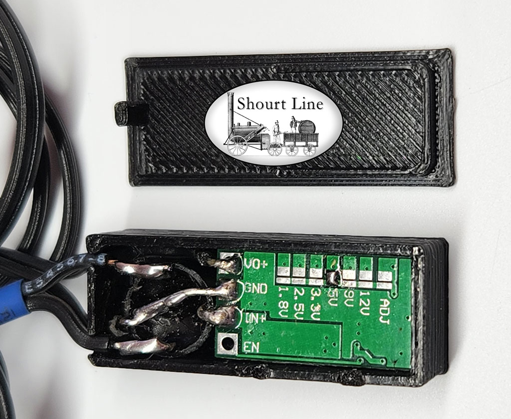
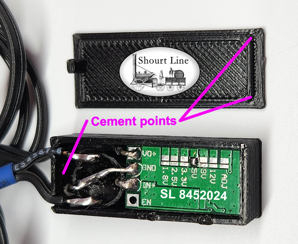
SL 8453018 Micro Size LED controller in case rear view with bottom plate off, showing the bridge wired to the controller, and 18 inch cable. Note the blue tube on the input power cable that comes out below the LED output cable that has no marker tube. The EN control pad can be optionally connected to GND to disable the output.
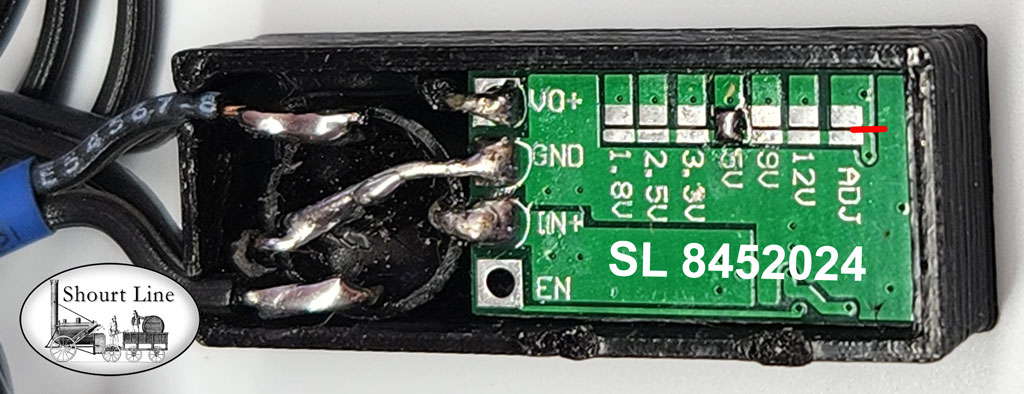
When you received the SL 8453018 it will be soldered to 5V track pads as shown above. This gives the output a voltage of 3.05V and can be adjusted in the range of 0.9 to 4.2 volts. This is perfect for controlling White LEDs.
The SL 8452024 controller inside the case can also be set to a fixed voltage of 1.8, 2.5, 3.3, 5, 9, or 12 volts when a voltage is selected by soldering pads and IF the adjustment pot is disabled by cutting the trace shown in red above to the right side of the ADJ solder pads AND the ADJ solder pads are NOT soldered.
Note that IF the red trace shown above is cut and you want to re enable the adjustment pot you can solder the trace pads above the 'ADJ'. The 5V track pads shown above are an example of how to solder two pads. Soldering the ADJ pads will restore the controller for adjusting to white LEDs. In addition, if the pot is enabled and no voltage tabs are soldered, then the output voltage can be set from 0.9 volts to input voltage less ~2 volts. This setting can be used for LEDs but you will find it hard to get the desired brightness (output voltage) as the adjustment is very course due to the wide voltage range.
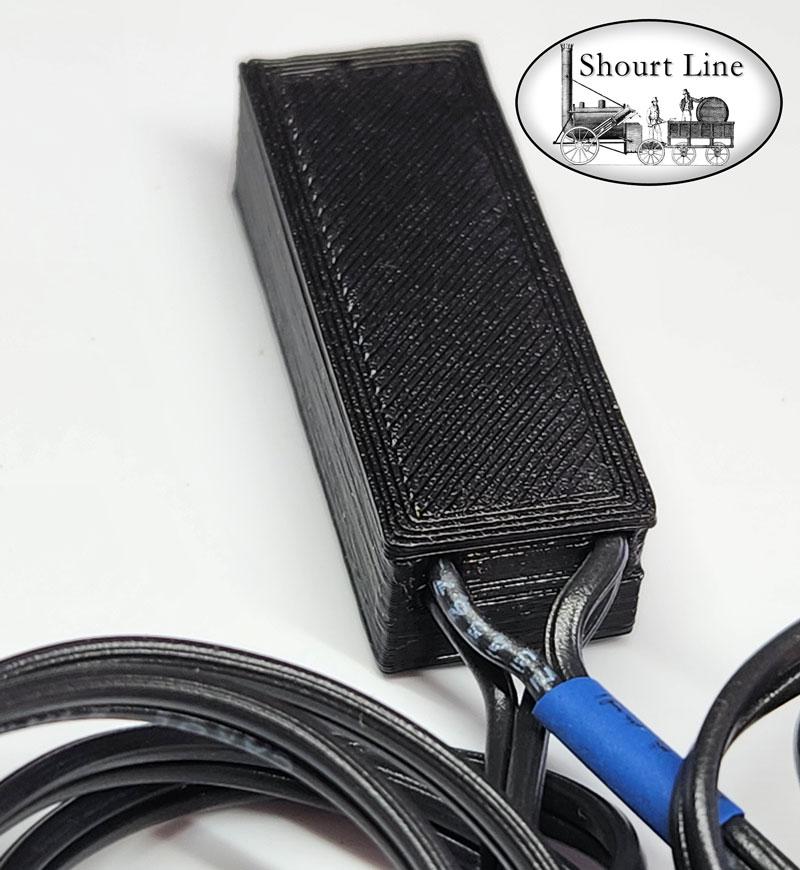
SL 8453018 Micro Size LED controller front bottom close up view, showing the 18" power input cable with blue tube on top of the 18" LED output power cable.
SL 8453018 Micro Size LED controller front top close up view, showing the 18" power input cable with blue marker below the blue the 18" LED output power cable. Note the LED cable has a copper wire for + side of LEDs and a silver ribbed output wire for the - side of LEDs that connect in parallel without dropping resistors. Note also the access hole in the top of the controller for accessing the volt adjustment pot. Always adjust the voltage with test LEDs before connecting to your lighting fixtures. Start at 3.05V output and slowly adjust down or upward for desired brightness using a test LED but do not exceed 3.1 volts or the manufacture's recommended maximum voltage to avoid damaging the LED. Follow the instructions we provide for setting the desired brightness without exceeding the manufacture suggested maximum forward voltage (Vf) and current.
.
SL 8453018 Micro Size LED controller front close up view, showing the adjustment pot access hole.
For notes on using the SL 8453018 click here
For notes on adjusting the output voltage for LEDs with Shourt Line LED controllers click here
Mounting examples:
The SL 8453018 Micro Size LED controller is delivered with a 3M adhesive mounting pad and without the back cover cemented in place. We recommend either asking us to do this for you at the time of order or you can do it yourself by applying a 1/3 drop of E6000 clear cement with a tooth pick to the locations shown below and wait 24 hours before mounting the case. The E6000 should hold the lid to the case and the 3M adhesive mounting pad will allow the case to be un-mounted when needed without damaging the case, the mounting surface or the rear lid.
The back side of the lid has a 3M outdoor adhesive pad for mounting. After confirming the lid is firmly cemented in place, peel off the red tap protecting the 3M pad and press onto a mounting surface that has been cleansed with an alcohol wipe. The 3M pad can be removed if desired and the case can be mounted or cemented in place without the 3M pad. The advantage of using the 3M pad is that it will hold the case securely and can be later removed without any damage to the mounting surface.
The SL 8453018 Micro Size LED controller size fits where other devices do not. It can be mounted in side loco cabs, in locos, in track side buildings and under passenger cars and on car ceilings.
The size of the SL 8453018 Micro Size LED controller is 34mm L x 13mm W x 9.25mm H (1.34"L x 0.5"W x 0.37"H).
Examples of where to mount the SL 8453018 Micro Size LED controller in passenger cars:
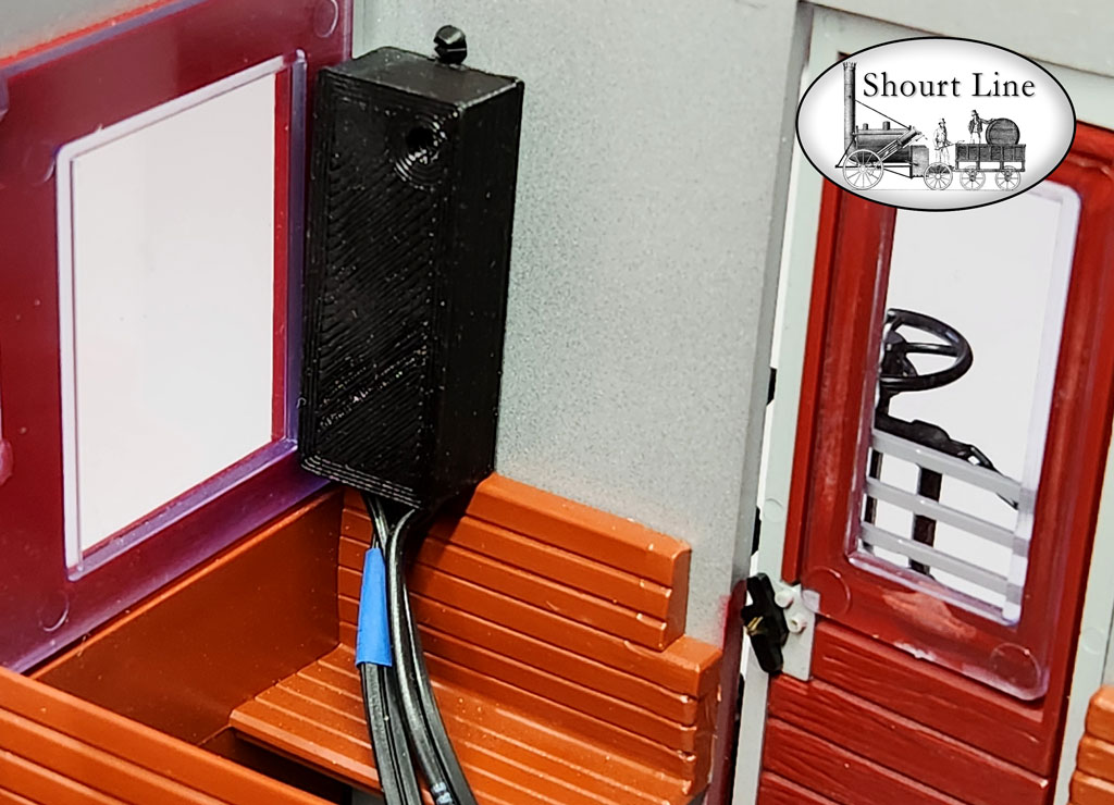
SL 8453018 Micro Size LED controller in case with 18 in cables mounted on the rear wall of a LGB short passenger car. Note that the case fits between the window trim and the back wall of the car.
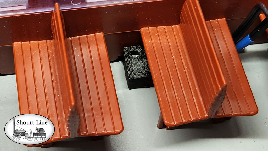
SL 8453018 Micro Size LED controller mounted under seats in an LGB passenger car.
Note that the adjustment pot is accessible between the car seats for brightness and dimming control.
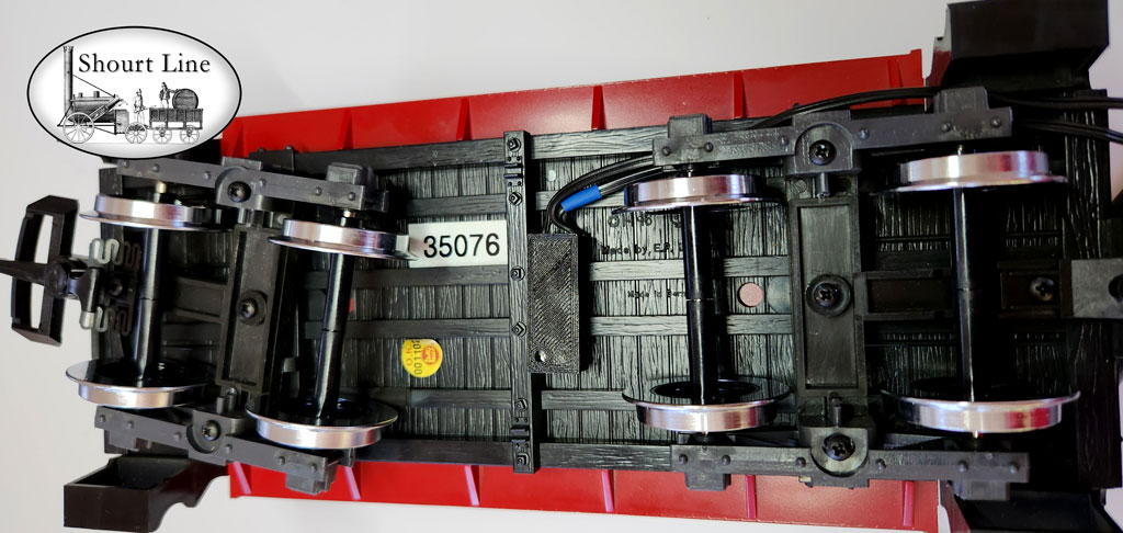
SL 8453018 Micro Size LED controller mounted on the bottom of an LGB passenger car

Simply your model railroad wiring with the Shourt LIne SL 8453018 Micro Size LED controller
Questions? Call 310-622-4431 or email info@ShourtLine.com
Thanks for looking - Shourt Line by Soft Works Ltd.
copyright 2024 SWL4.com - Soft Works Ltd. all rights reserved
